Development History
Motorcycles and other two-wheel vehicles have been quite popular in developing countries, and now small vehicle emissions are becoming a mainstream issue. The position of a two-wheel vehicle for the user in terms of individual finances is the equivalent of a K-car (kei-jidosha) in Japan. When purchasing one and also taking into account the price of gasoline, it is two times higher than in Japan, relatively speaking. However, by purchasing a motorcycle and extending the area of activity for the user, this lead to more income opportunities. As a result, there is a growing demand for small motorcycles and other two-wheel vehicles that are affordable.
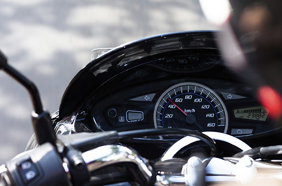
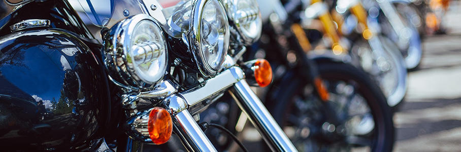
The “headlight (H/L)” at the front end of a motorcycle cannot be ignored. Its design completely changes the look and feel of a motorcycle and other two-wheel vehicles. On large motorcycles, an LED H/L has been adopted for the H/L valve in order to give the product more appeal, through its superior design, longer-lasting lifespan or low power consumption. However, this change to an LED has appeared in smaller motorcycles and other two-wheel vehicles.
In order to keep up with this H/L change, we have developed inexpensive and high quality products, and even our AC/DC regulators and rectifiers designed for small motorcycles and other two-wheel vehicles support an LED specification and also feature a battery charging function and H/L control function.
Development Technology
An LED is a light emitting device driven by current, and a stable current flow is required to light it up. To achieve this, a special LED driver is generally needed to use an LED H/L.
Conventional AC/DC lamp control regulators and rectifiers for small motorcycles control the ACG negative output to light up the valve H/L. By using fixed current control on the valve H/L control section, the LED can be lit up without the need for a special LED driver. In addition, the ACG output is used, instead of a battery, to light up the LED. Therefore, stable lighting can be controlled even when the battery performance has deteriorated or even without a battery.
In fixed current control, when the LED is controlled on the Hi and Lo sides, the number of terminals increases. However, in this system, the LEDs are connected in series and controlled on a circuit. In addition, the current consumption can be mitigated by connecting in series instead of in a parallel format.
In our development, in order to optimize LED lighting control for small motorcycles and other two-wheel vehicles, we went beyond developing just regulators and rectifiers, but provided a total solution that also included the LED H/L side structure.
-
-
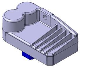
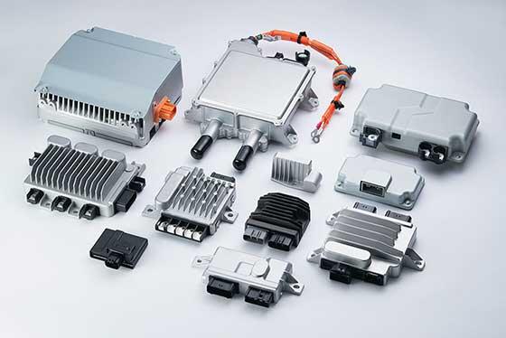
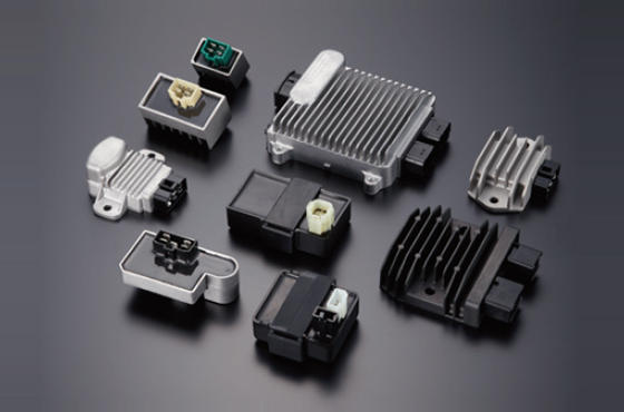
- External view of regulator/rectifier
-
-
-
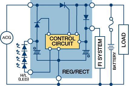
- System layout
-
Problem-solving Approach
LED variation countermeasure
The LED is differs from a valve because the light turns off immediately after conduction stops. When the lighting is controlled by the negative cycle of the ACG output, the light turns off during the positive cycle of the ACG output. As a result, variation notably occurs in a low rotation range where non-conduction becomes longer. A regulator and rectifier features a built-in electrolytic capacitor and smooths out the voltage on both ends of the LED. In addition, conduction flows in phases appropriate to each cycle, producing LED lighting control without variation.
Solving issues when LEDs are connected in series
The following issues have been resolved when LEDs are connected in series.
- More voltage is needed than the amount of the forward voltage drop (VF) for LEDs connected in series, and in the battery voltage, because it is difficult to overcome the VF on the LED, a driver is required to boost the voltage.
→When connecting directly to and controlling the ACG output, a high voltage can be obtained easier than the VF on LEDs that are connected in series. By applying this to LED, the LED can be lit up with a singular regulator and rectifier. - When the line for 1 light is disconnected, all LEDs turns off.
→When the line to the LED on the Lo side is disconnected, the output voltage for the LED on the regulator and rectifier side is boosted. Once a boost is detected in the output voltage on the regulator and rectifier for the LED H/L side, the thyristor in the LED H/L is turned ON. In this way, an LED that has failed or been damaged is bypassed and the remaining LEDs can light up.
-
-
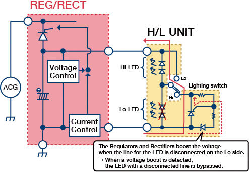
- System layout (When a line is disconnected)
-
Lighting error prevention when lighting switch is exposed to rain or water.
Motorcycles and two-wheel vehicles are exposed to water when it rains and when in other wet conditions. LEDs light up even with minute currents. As a result, lighting errors must be prevented when there is leakage currents after the lighting switch is exposed to water.
→When a lighting switch is used and both ends of the LED short circuit on the Hi side, the system ensures that the light is turned off.
-
-
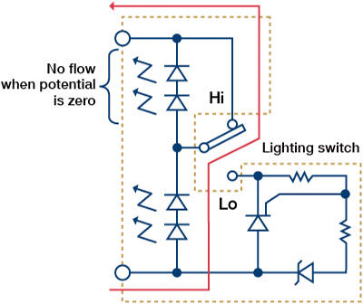
- Usage of light switch
-
Expected Effectiveness and Future Measures, etc.
By only changing the regulators and rectifiers and without adding special LED drivers, we have produced a high quality and inexpensive LED H/L lighting system for small motorcycles and other two-wheel vehicles. This can promote the use of LED H/Ls in small motorcycles and other two-wheel vehicles.
Going forward, we will continue to provide charging and lighting solutions that optimize and are fitting for changes, such as environmental regulations and improving product appeal.