Circuit and Control Technologies for High Efficiency and Low Noise
1. Partial resonance full bridge type
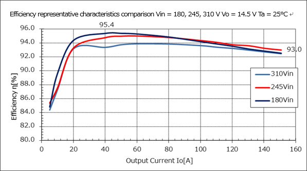
The main circuit configuration for this power supply uses a partial resonance full bridge type which achieves zero voltage switching operation with a smaller number of components. This contributes to greater fuel efficiency for automobiles by working to reduce switching loss of internal components and setting the conversion efficiency to its highest point in the range of actual use.
Circuit configuration block diagram
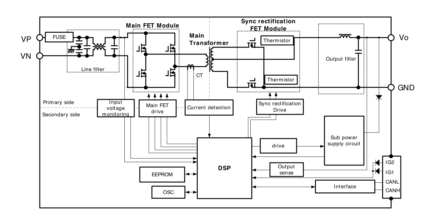
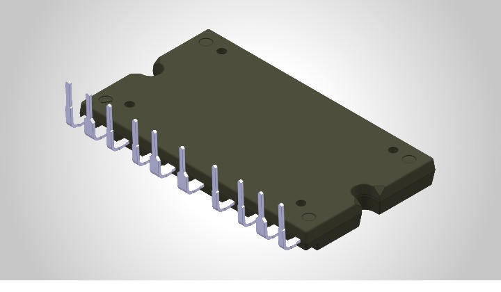
Main FET Module
Efficiency characteristics
2. Performance improvement through digital control
Control for DC/DC converter power control and communications is all fully digital (DSP). Optimal power feed system control is achieved through optimal control of circuit operation, improved functionality, power supply monitoring, safe design, and communication with higher ECU, which were not able to be achieved with previous analog technologies.
3. Use of internally manufactured components
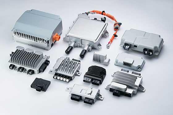
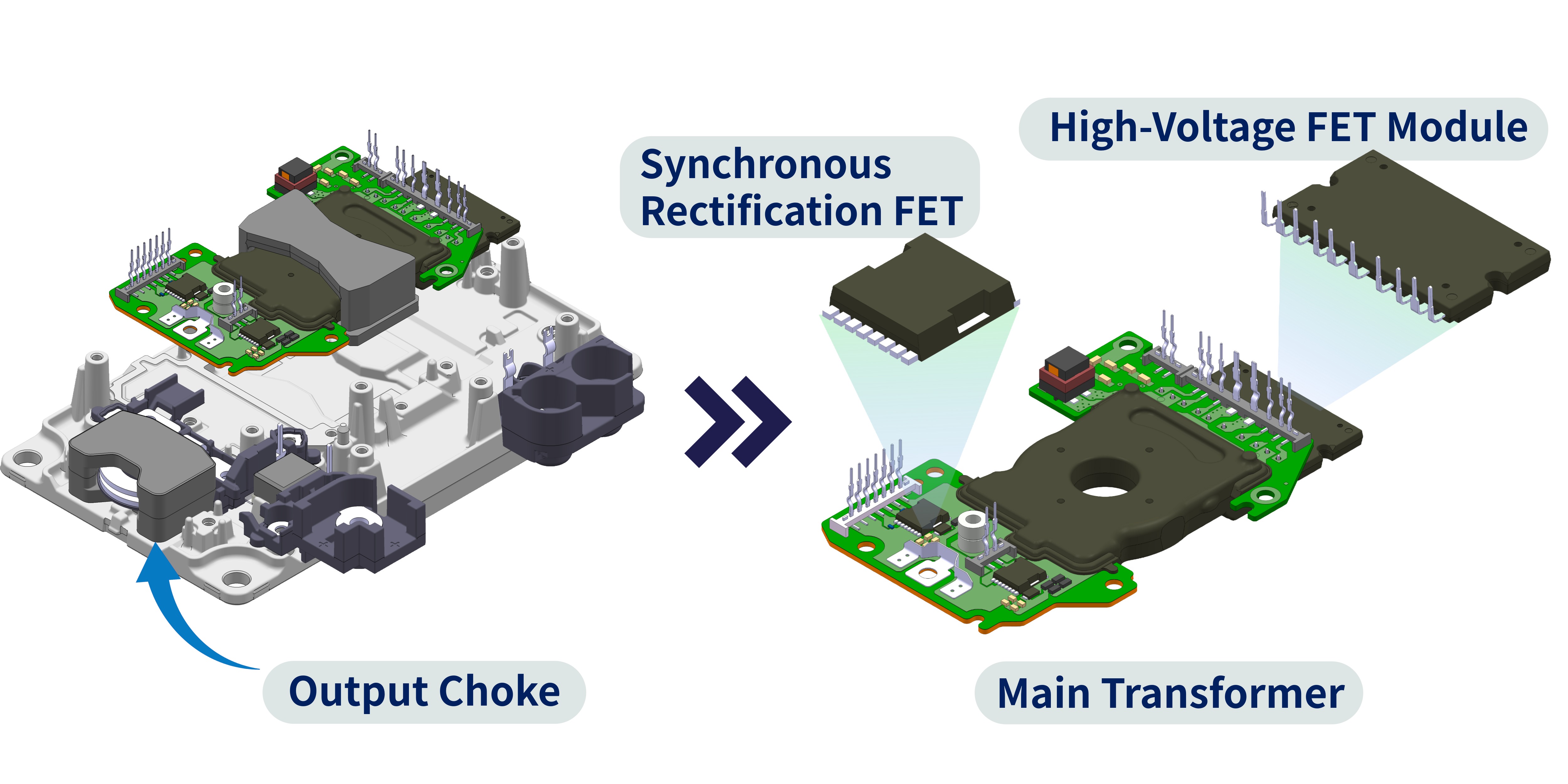
The main circuit components of our DC/DC converters—such as high‑voltage FET modules, main transformers, synchronous rectification FETs, and output chokes—are optimally designed by Shindengen’s internal Power Devices Division and Power Units Division to meet the specific requirements of each power supply design.
By integrating these components into an aluminum die‑cast housing, we have achieved a structure that significantly enhances heat dissipation performance for both air‑cooling and water‑cooling systems.
Optimal Mounting and Packaging
Contributing to High Heat Dissipation Performance and Improved Production Efficiency
- Newly developed transfer transformer utilizing our proprietary packaging technology
- Integrated high heat dissipation, insulation, and fastening functions of the main transformer to achieve improved production efficiency.
High Efficiency Achieved Through Optimized Design
- Adopts an input-side module equipped with our in-house developed high-voltage VX6 series and synchronous rectification FETs using the low-voltage EETMOS5 series.

Parallel Connection for Flexible Power Expansion
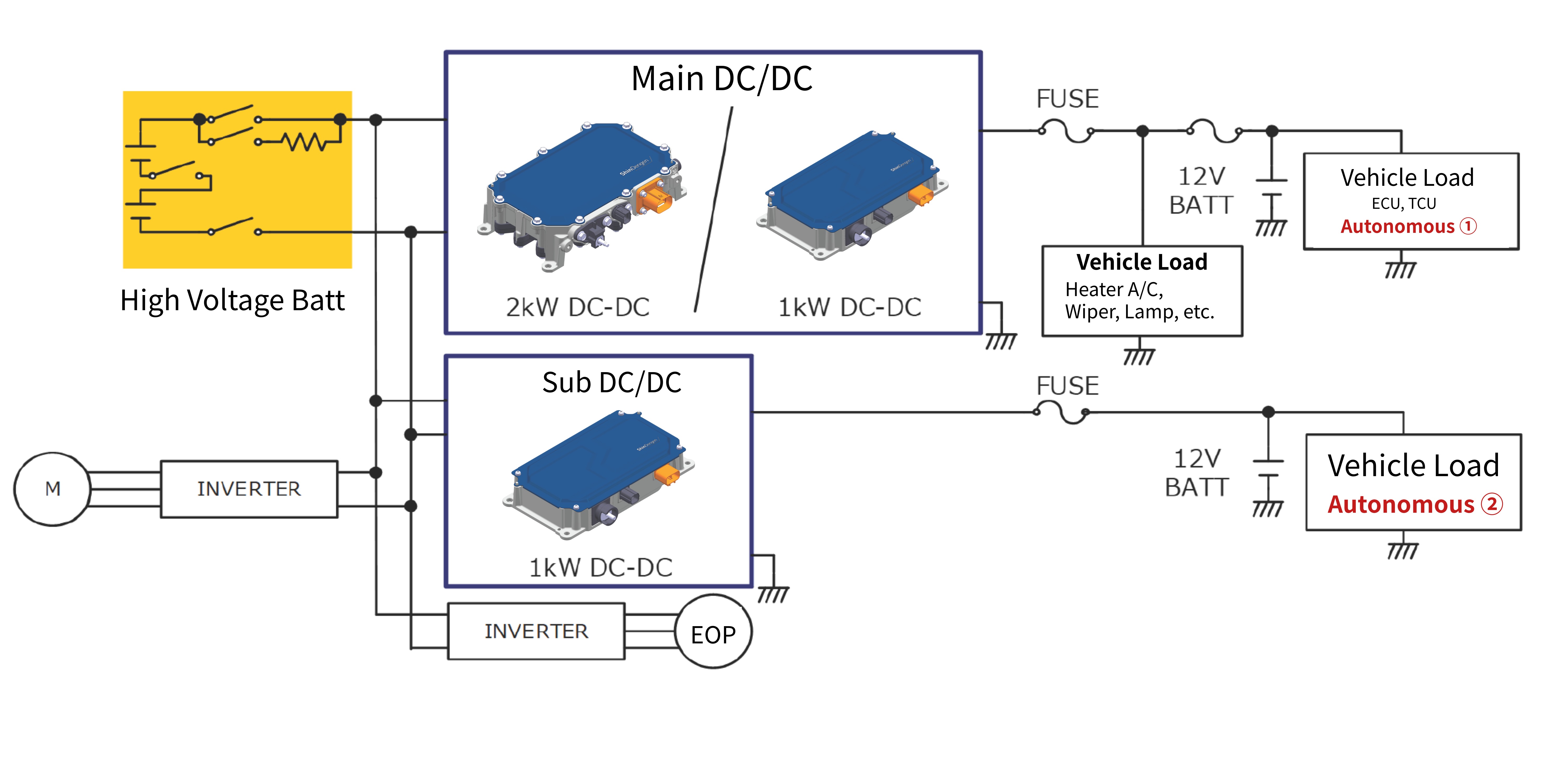
High-Current System Example: Parallel Operation
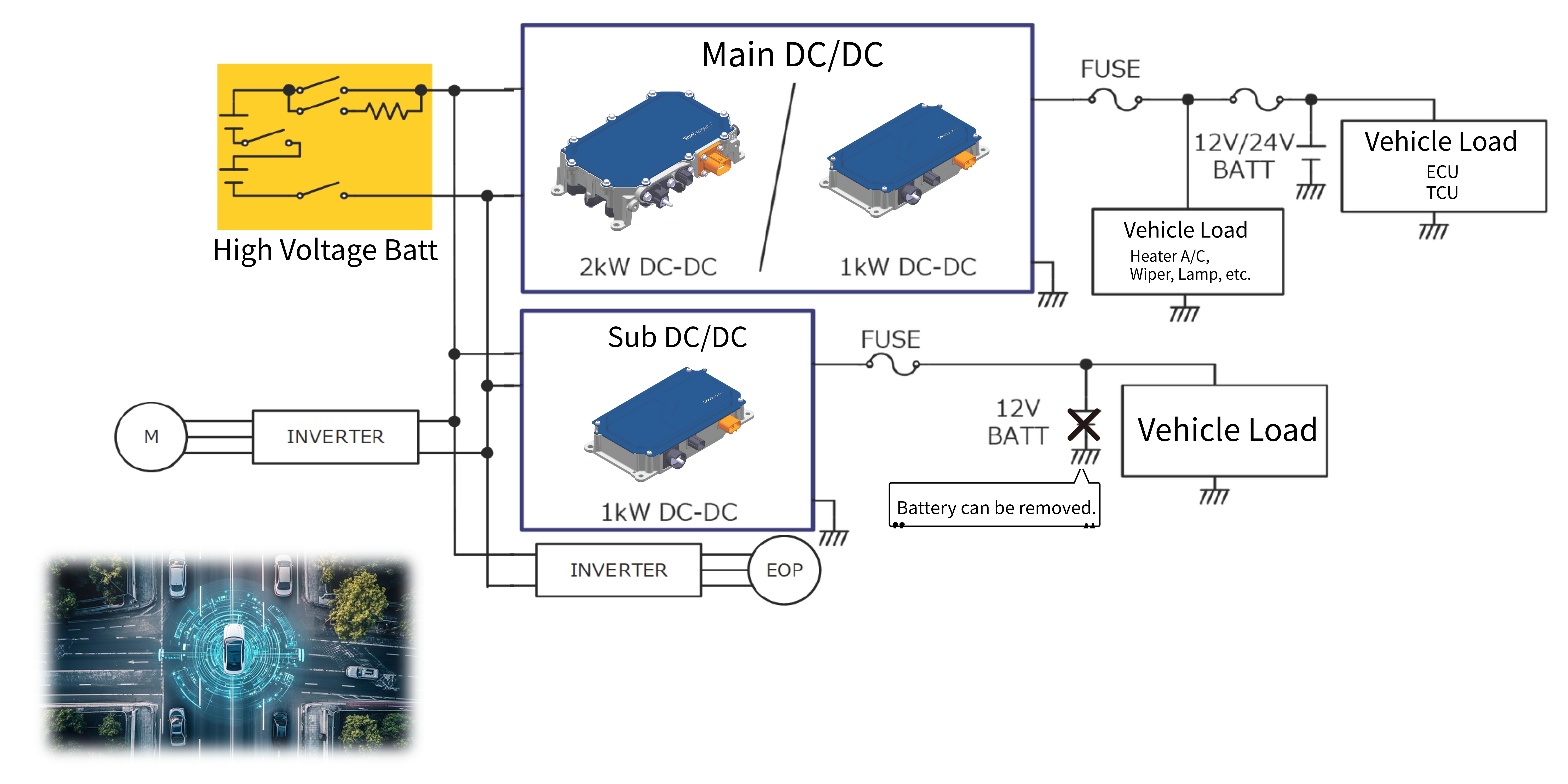
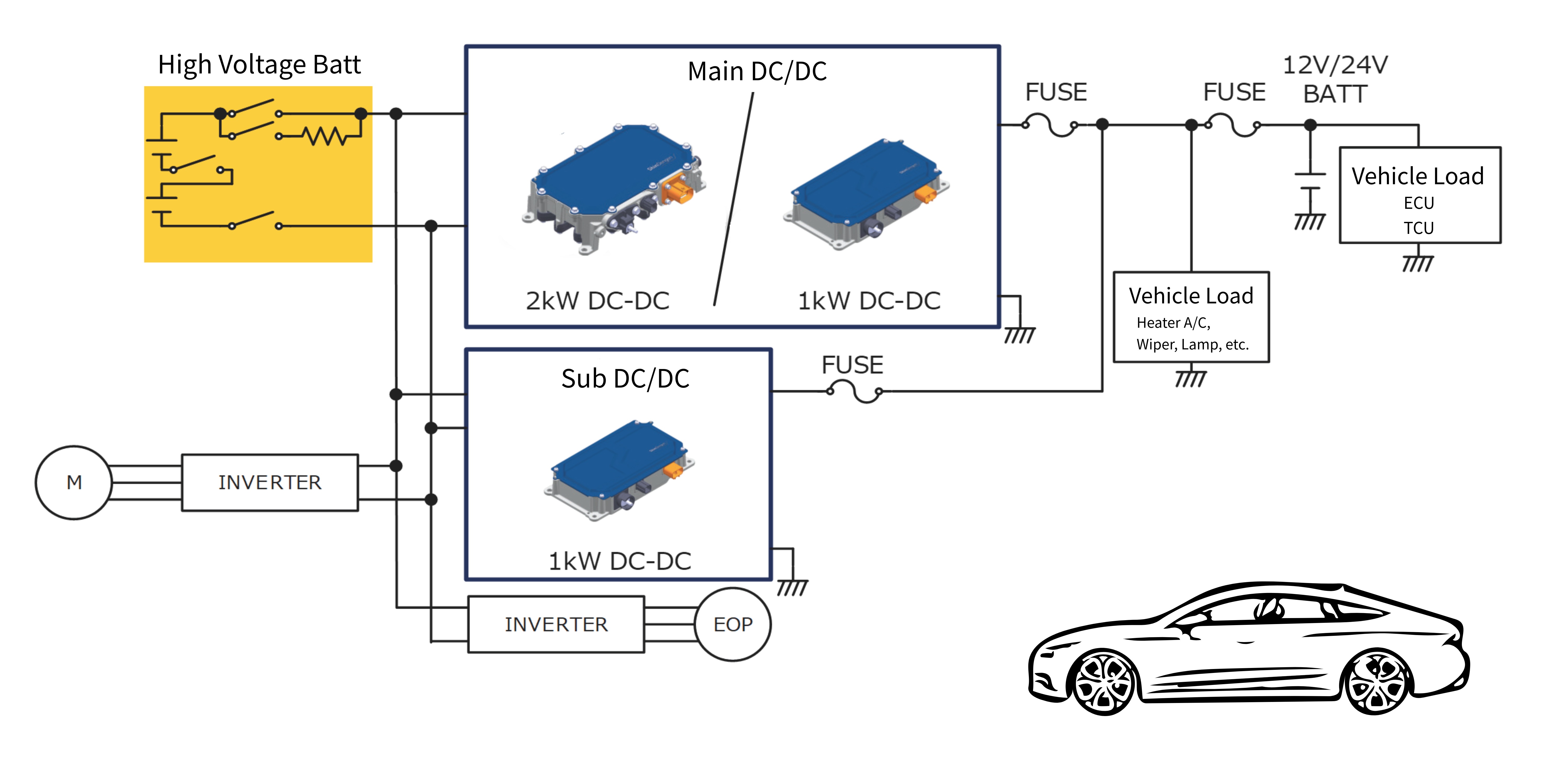
With the increase in auxiliary power due to the evolution of car electronics and the evolution of autonomous driving technology, DC/DC converters with higher output are also required. By using DC/DC converters capable of parallel operation, we respond to the growing demand for auxiliary power systems.
-
Example system in which an auxiliary DC/DC converter is connected in parallel as a booster when a high-current DC/DC converter is required.
-
By distributing auxiliary power loads, it helps suppress the need for larger wire harnesses and main fuses that would otherwise be required for high-current DC/DC converters.
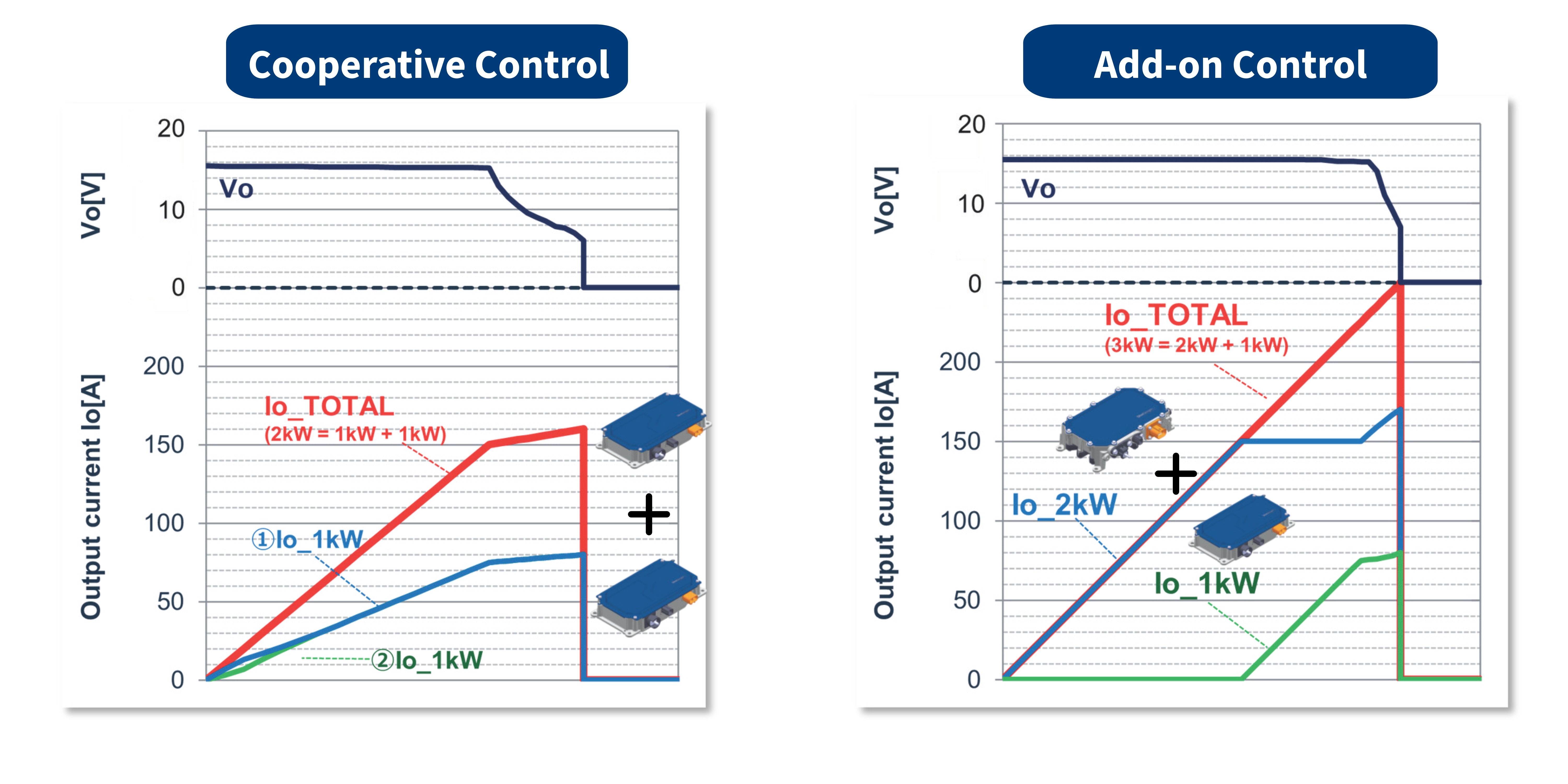
Output characteristics during parallel operation
This is the output current and voltage characteristic when 1kW and 2kW are combined and operated in parallel. It is possible to correct the output current value of the two converters so that they can be supplied in a balanced manner. Even if a vehicle load is added and the required current increases, if there is a DC/DC that can operate in parallel, it is possible to easily supply power from the sub DC/DC converter.
Redundancy Support to Minimize System Downtime Risk
Redundant System Example: Redundant Operation
When configuring a fully redundant autonomous driving system, it is necessary to also make the auxiliary power supply redundant. By using DC/DC converters, we can meet the needs of various auxiliary power supply systems.
Autonomous Driving
- Used as a dedicated sub-power DC/DC converter in redundant power systems for autonomous vehicles.
Dual Battery System
- Capable of supplying power to 24V systems, as well as providing 12V power without a battery.