- TOP
- Lineup
- New Product
- Launching MCZ5216ST LLC Current Resonant Mode Controller IC
New Product
Launching MCZ5216ST LLC Current Resonant Mode Controller IC
Jun. 17, 2019
1.Overview
LLC current resonance circuits are used to achieve higher efficiency and lower noise in 100-500W output class power supplies.
The newly developed MCZ5216ST is an LLC current resonance control IC which combines the functionality of the previous MCZ5211ST with built-in X condenser discharge functionality.
Incorporation of this X condenser discharge functionality allows for an approximately 25% reduction in power consumption during standby.
Moreover, our original control method (asymmetric control) provides the chip with an active standby function which improves power efficiency during light loads (of several W) and standby, which makes it possible to eliminate the need for the auxiliary power supplies required up until now. The chip also allows for the operating frequency to be increased up to 500kHz, contributes to power supply miniaturization, and is equipped with a variety of protection functions, making it possible to construct a power supply circuit with a small number of component parts.
※During no load condition, compared to our conventional model.
2.Features
- Built-in X condenser discharge functionality
- Input voltage detection mode can be selected from either AC or DC
- Allows for transmission of IC operating status through a photo-coupler using a power-good signal (in AC input detection mode)
- LLC individual IC equipped with HV Startup (600V withstand voltage starter circuit)
- Compatible with higher frequencies - Capable of constant operation frequencies of 500 kHz
- Low standby power (built-in active standby function and burst function)
- Built-in oscillation frequency compensation function using input voltage during burst (in DC input detection mode)
3.Typical Applications
- Power supplies for LBP and other document equipment
- Power supplies for audio equipment
- Power supplies for FPD
- Power supplies for LED lighting
- Power supplies for industrial equipment
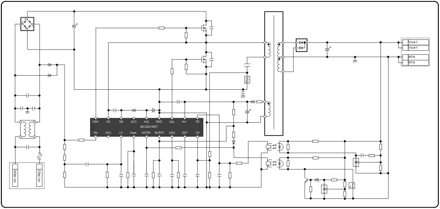
4.Basic diagram
5.Product specifications
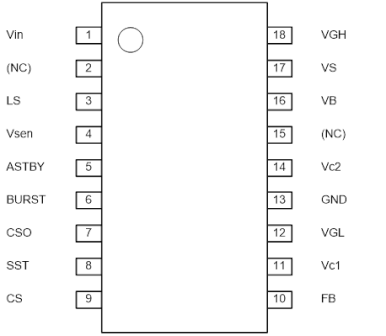
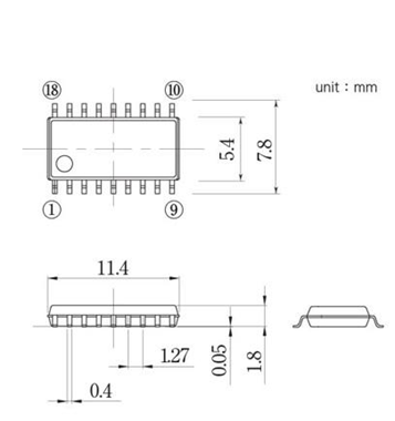
6.Pin Assignment and Exterior Diagram SOP18 Package
| PIN No | Symbol | Function |
|---|---|---|
|
1 |
Vin | Input of start-up circuit, X-cap discharge |
| 2 | NC | Non connection |
| 3 | LS | AC detect, Vsen charge |
| 4 | Vsen | Low voltage protection. SS-reset |
| 5 | ASTBY | Change to active stand-by mode, burst mode |
| 6 | BURST | Control to burst operation |
| 7 | CSO | Detect to adjust response of averaging current |
| 8 | SST | Control to soft-start time and intermittent operation time |
| 9 | CS | Detect to over current, averaging current, di/dt-mode |
| 10 | FB | Frequency and duty setting |
| 11 | Vc1 | Power supply to Vc2 |
| 12 | VGL | Output of low side driver |
| 13 | GND | GND |
| 14 | Vc2 | Output voltage of control circuit, driver |
| 15 | NC | Non connection |
| 16 | VB | High side driver supply voltage |
| 17 | VS | Reference of high side driver |
| 18 | VGH | Output of high side driver |
7.Factory Location
Higashine Shindengen Co., Ltd. etc.
8.Availability
Available
9.Contact information
Notes
・The content of these materials may be changed at any time without prior notice for product improvements or other reasons.
・Our company shall not be held responsible or liable for any damages, or infringement of patents or other rights which occur as a result of the use of these materials.
・Reproduction of any portion of these materials without prior written authorization is strictly prohibited.
* The contents listed are as of Jun 17, 2019
Please note that the information contained in releases is current as of the date of press announcement, but may be subject to change without prior notice.